Why build this project:
1) Because it's an LED tester on your proto shield that doesn't mind orientation. Ideal for quickly testing a suspicious LED or checking the color on a transparent LED.
2) Arduino independent, it's based in the 555 bi-polar LED driver, so it doesn't interfere with any of your Arduino pins or code.
3) Because it's easy and affordable way of learning how a 555 works.
How to build this project:
It goes like this:
Use this build as a learning experience on the 555!
What happens at the LED side?
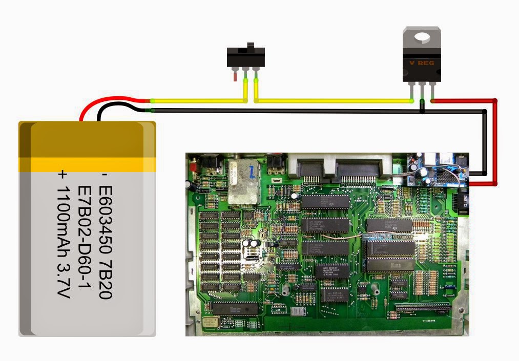
Look at the diagram above. Let's imagine you have two LEDs, one GREEN, one RED connected just as above. Commonly referred to as Vcc, the supply voltage can range between 5V and 15V. In this example, we will use 9V.
1) Simply put, we are connecting the left leg of the LED to the output pin (3), which oscillates between 0V and the supply voltage (Well, actually the supply voltage minus 1.7V so it's around 7.3V in this case. Refer to the 555 timer wikipedia article for details.)2) The other leg of your LED (the one on the right) is connected to the resistor divider, which divides the 9V. So only 4.5V are present at that leg.
3) As a consequence of step 2 above, when pin (3) his HIGH, your LED sees a potential difference of 4.5V, and when (3) is LOW, it sees a potential difference of -4.5V and BAM! That's why the current alternates in both directions allowing you to place LEDs in any orientation.
Note: Since I usually feed my Arduinos with 12V, I replaced the two 220 Ohm resistors for 290 Ohm in order to reduce the power consumption of the resistor divider to less than 1/4W. This impacts consumption but the voltage divider still divides to 4.5V.
OK, got it. Now, what happens at the capacitor/resistor side?
1) The combination of the Cap and the resistor produces a delayed charge and discharge of the capacitor. The very same output pin (3) we use to drive the LED is used here to both charge the capacitor when output is HIGH and discharge it when the output is LOW.
2) Both inputs of the 555 Trigger (Pin2) and Threshold (Pin 6) are shorted together, which leaves us with a single input that reads the voltage at the capacitor.
3) Remeber that in this example we are feeding the circuit with 9V. Whenever the input reads below 3V from the capacitor, it will turn the output HIGH, turning the green LED ON. At the same time, the capacitor begins to charge, slowly rising the voltage at the input pin (2 and 6).
4) As soon as this rising voltage gets above 6V, it will reset the 555, setting the output to LOW which activates the red LED, and at the same time it begins to discharge the capacitor, which will eventually get to below 3V, leaving us at step 3 again.
So, why are these boundaries at 3 and 6 volts?
Because I used 9V as an example for feeding the circuit. 3V and 6V are 1/3 and 2/3 of 9V respectively.
If I had used 12V to feed my circuit, boundaries would have been 4V and 8V respectively because it's always 1/3 and 2/3 of the supplied voltage.
Can I make them blink quicker or slower?

Of course you can. Check out these great resources:
1.- HyperPhysics at Georgia State University - A simple tool for calculating time to charge/discharge your capacitor.
2.- Wikipedia - RC time constant
Top view:


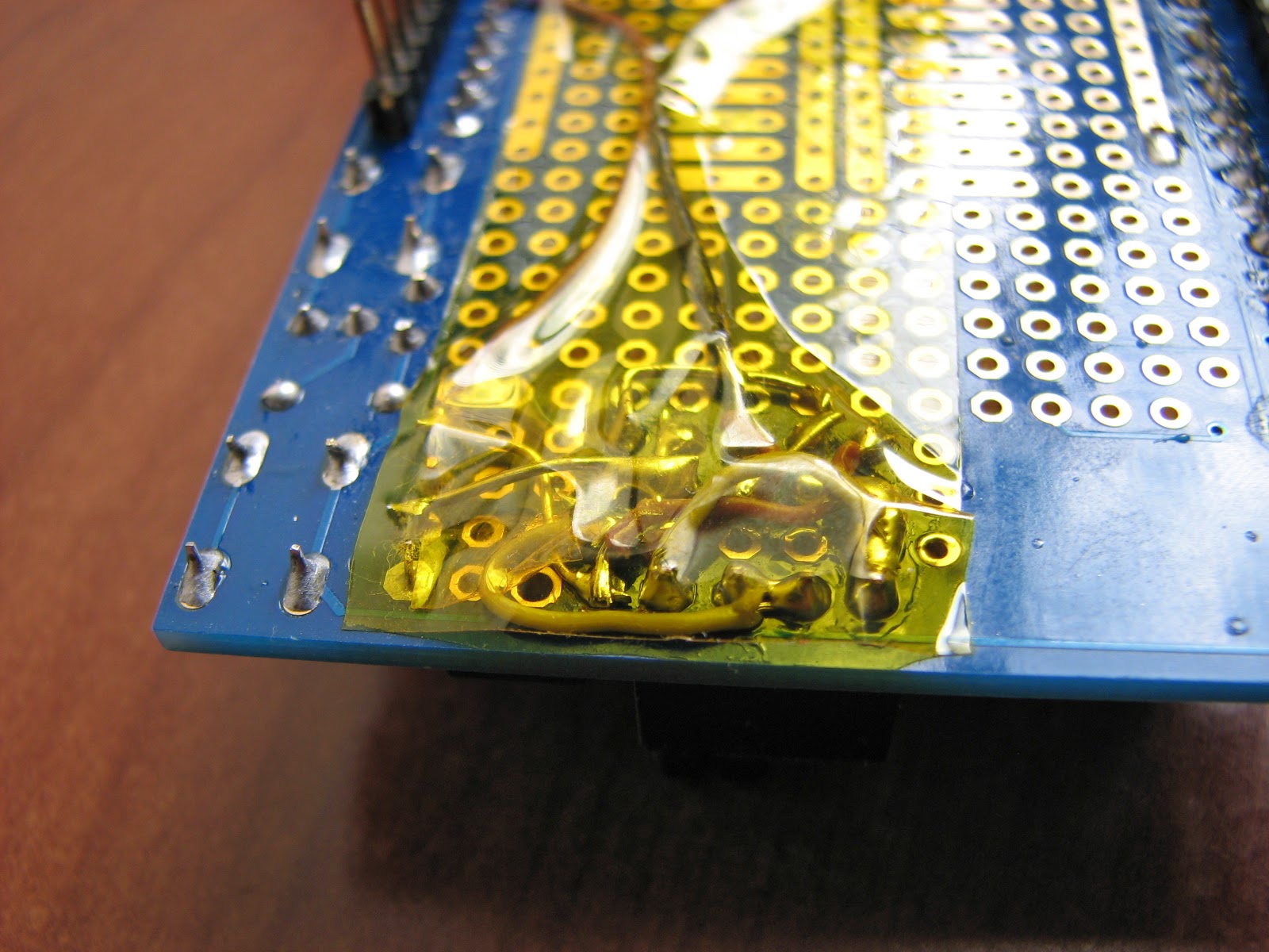
Bottom view:
Finally, if you want to see some of my other mods for the Proto Shield, click here.