Background:
You may have read my post about how to power an Atari diskette drive with a switching power supply.
You may have noticed that I'm not a big fan of heavy, large Atari power bricks.
And don't get me wrong: they are beautiful designs, reliable, powerful, and Atari branded. However, in modern days where an 8-bit is not your primary computer for getting things done, these bricks make it unappealing to get your vintage gear running every once in a while.
The objective of this easy project is to be able to pull your Atari from an UV-free storage and hook it up to your TV allowing quick play using a SIO2SD interface.
So here it goes: A battery powered 8-bit (With the battery inside the case).

Materials needed:
- An Atari 8-bit computer willing to be modded in the guts. (I've used a spare 65XE since I would never mod an 800XL in any way).
- A battery. Lithium Polymer 11.1v / 3-cell, 1800mAh and above.
- A switching voltage regulator aka DC to DC converter: I used a 5v OKI-78SR series from Murata Power Solutions.
- Decent soldering skills, a soldering station and powerful de-soldering pump.
Do some research first, ask yourself some questions:
Q: Can an Atari be battery powered for a decent amount of time?
A: Atari power bricks supply a maximum of 1.5A, if you measure the actual consumption at 5V it goes around 450mA which is not hard for a LiPo 12V battery to handle.
Q: How long will the battery last?
Once using a regulator, it draws only 250mA from your battery, giving you a theoretical life of 4 hours of continuous play on a 2100mAh battery. I'm fine with 1 or 2 hours and this easily doubles that!
Q: Will a battery fit inside the case?
A: There's only one way to figure it out: Crack your machine open and see what fits in. The 65XE has quite a roomy case for this mod. I'd say it actually fits two batteries.
Q: Should I use a linear regulator or switching regulator?
A: The problem with linear regulators such as the LM7805 is that you waste too much energy in heat and in this case it will get fairly warm, which will force you to add a heat dissipation on a tight space. The switching regulator is far more efficient and not noisy enough to disturb the functionality on your Atari. Audio comes out fairly clean with these.
The design:
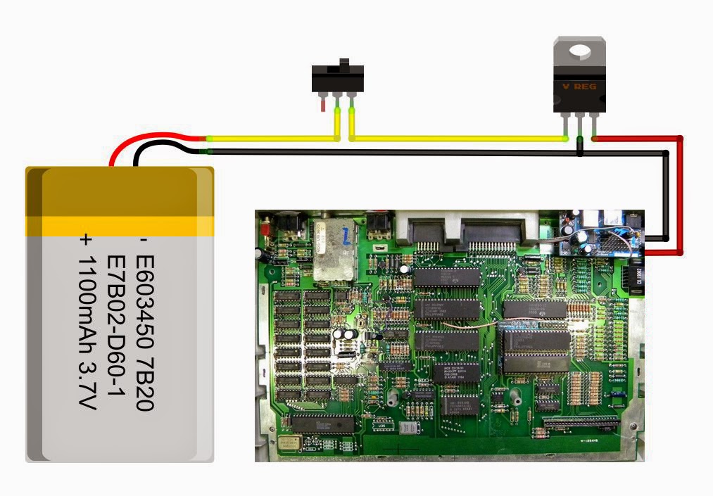
This design considers interrupting the 12V line. If you do it at the 5v stage after the regulator, you can easily solder the circuit directly to the 5v connector on the motherboard. However, this won't work best because the regulator will continuously draw current from your battery until depletion. Not good.
On the other hand, interrupting the battery feed directly like the diagram shows, will force you to add a secondary switch or de-solder the original switch.
Caveats on the design:
- This design requires you to understand LiPo batteries because these are delicate and potentially dangerous.
- You will need good soldering skills and take the necessary precautions while connecting everything together and isolating the connections properly.
- You will need a special charger to take care of the life of the battery as well as to prevent overcharge.

Regulator placement


The three legs of the power switch were de-soldered from the main board and isolated. This power switch now handles 12v instead of 5v.

Final battery placement
Project finished, ready for the final cover.
Charging
Charging gets accomplished using a special LiPoly charger directly to the balancer connector of the battery. That connector reaches the exterior of the case via the expansion port. If you look closely the last picture you will see a white connector sticking out.
After finished, I left it on by accident and noticed almost 3 hours later.
The battery was at 11.7v, plenty of life left. But this definitely reminds me of the....
To Do
Add a low battery automatic shutdown to prevent damage to the battery.
Thanks for watching, stay tuned.