The finished project at 11:39, before turning itself into a countdown timer. This timer has been in production since December 31st 2011 (upd: in production until 2020, decommissioned in July 2024)
October, 2011.
Inspired by
Sparkfun's GPS clock, I decided to build my own version of a big countdown timer for New Year.
1) The concept
Dual function: A clock that starts at 11:00PM and simply shows the time for the entire hour. The idea behind it is to drive people's attention and let them know where the clock is.
I didn't need a 24h clock, only something that tells the time from 11:00p to 11:58p and turns into a countdown timer for the last minute (the hour digits turns off and the countdown starts from second 59 to 00).
This approach saved me 6 segments and some space as well.
2) The clock itself:
I went as readable as I could, readable but portable. I used bright white LEDs (not ultra-bright) and some transistors. I happen to like Ben Krasnow's
way of dealing with transistors.
This is what the first concept looks like:
3) Controlling the clock:
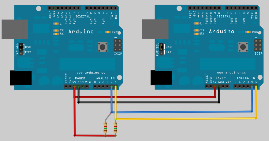
I used an Arduino and shift registers to control the segments, you can also use two Arduinos via I2C.
Two shift registers (74HC595) command the segments.
An Arduino controls the shift registers, cycling about 150 times per second.
4) Time accuracy:
I wanted this thing to be accurate. The Atmega chip keeps track of time but they are not accurate enough over long periods of time, reason why I added a
RealTime Clock Module.
Now, in order to have the RTC set at the right time, I added
NTP Atomic Clock Synchronization capabilities through an
Ethernet Shield.
Edit: After the first year into production, I decided to simplify the design by replacing the RTC+Ethernet shield with an LCD shield. This allows to manually adjust the clock while having a simpler setup.
In order to keep accuracy I use an NTP app in my iPhone and manually adjust the Arduino until it's synchronized by using the buttons available on the LCD shield.
5) The Design:
Before the shift registers, I used a two-arduino approach with served me well while shift registers were not available at the local store.
One GREAT source to understand how the shift registers work is here at
BLDR.ORG:
Back to the design board:
- I wanted to balance the amount of LEDs with functionality, and I ended up with 3 LEDs per segment.
- I could have gone with larger digits but I found that the size I went with was good enough.
- I wanted this to be both inexpensive and battery operated so I chose super-bright leds instead of ultra-bright.
6) The build:
This design calls for portable and lightweight, so let's use these convenient cardboard box lid.
I had these boxes in my storage room. I borrowed 3 lids.
Design of the digits. I drew them proportional to a small 7 segment display, under the assumption that it will increase readability.
Adding the LEDs to each segment:
8 segments in place. Each segment consists of 3 LEDs
Time to solder some wire, add current limiting resistors, some transistors and more resistors for their base just like the original design in paper.
Wiring at the back. The deadbug chip at the center is a resistor array.
First test:
First digit is complete. number 3 shows up.
And then another instance of the same digit plus a third that only does number 11, to get the project complete.
Front of the completed project, the three digits can be easily separated and piled up for easy transportation.
Back of the unit
Back of the unit
Portable mode!
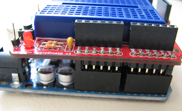
Main controller
Test scenario: balcony. View from ground, several floors below:
Photo Enhanced ASA800 (Canon S3IS)
Normal Photo (ASA 100)
7) Power:
When all of the LEDs are on, consumption of the whole circuit is reasonably low.
This allows me to power the entire system with a 2000[mAh] 11.1[V] Lithium Polymer battery, making the clock 100% autonomous for the whole hour it is used.
Happy new year! - Viña del Mar, Chile.


