This particular project somehow embodies three of the things that amaze me the most: Electronics, Space Exploration (particularly the STS since I watched the first Columbia launch live on TV back in 1981) and yes: Lego.
I acquired this set (# 10231) very recently without really understanding why didn't I get it when it first came out but anyway, this gorgeous Shuttle finally decorates my home office and it's staying.
One of the first things I thought after playing with it was "wouldn't it be cool if..."
Okay you get the idea, now to the project.
The implementation is simple and I executed it in two hours: Add LEDs to the spotlights of the set while adding a nice feature: have them power up automatically whenever there's no enough ambient light for an incredibly cool effect.
First thing was to figure out a simple circuit and for that Internet can be your friend:
Thanks to the people at Build Circuit Australia
This circuit senses ambient light with the phototransistor and if it gets dark, it fires up the LEDs.
Power consumption when idle is 0.9mA and when fully lit is 1.4mA.
The reason why this circuit draws current when idle is because that in the presence of light (or IR light) Q3 turns on and current will flow through it, and through the Base-Emitter junction of Q1.
When Dark both Q3 and Q1 are turned off. R1 then takes control, exciting the base of Q2, turning the LED on as a consequence.
I changed several resistor values here in order to make it work the way I wanted. I also used PN2222A NPN transistors just because I had those laying around. So feel free to play around with these values until it works the way you want.
Some soldering, I added a switch for MECO (that's NASA terminology I feel like using for this post).
Batteries on the flip side:
Prepare the MLP (more NASA terminology for you to find out in case you are not already familiarized) and modify accordingly for it to receive the new circuit and power supply:
Here you can see it fits right between the SRB underneath the stack. The added circuit remains invisible to the spectator.
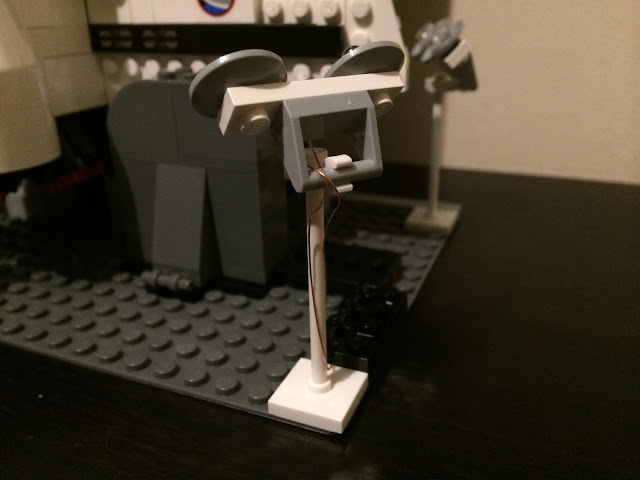
Now the trickiest part, yet still fairly easy to accomplish: Fit the LEDs. I used isolated fine copper wire from an inductive charger. You can find this type of wire in an old transformer as well.
Done.
And done. The wire is barely visible, and I use some Lego parts to hide it further. The cables go straight to and behind the TSMs and then routed to the circuit board.
Finished Project. You can see I'm using my hand to shadow the phototransistor for this particular test:
View from behind:
End result. Whenever it gets dark, the Shuttle remains visible.
Enjoy!!!!!


No comments:
Post a Comment