It works flawlessly in my projects, even with other I2C devices hooked up at the same time. This may not be as cheap as using a multiplexer, shift registers, a MuxShield or so many other ways of doing this but hey, this approach may save you if in need of more ports and you have more than one Arduino in your parts bin.
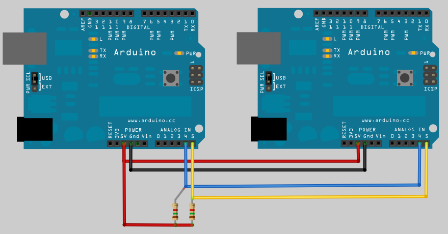
The connection diagram. The pull-up resistors shown are optional.
The connection is the same as what you would do with a standard I2C between two arduinos. I added pull-up resistors to each wire.
Basically what this does is to allow the master Arduino to access the remote's I/O pins, thus, expanding its original I/O capacity. You can hook up many Arduinos in parallel expanding to more I/O pins as needed.
The code at the Master Arduino:
#include <Wire.h>
#define LOCAL_PIN_TWO 2 // Pin 2 on local
#define REMOTE_PIN_TWO 102 // Pin 2 on remote
#define TEMPERATURE_PROBE_PIN 103 // Pin 3 on remote
#define SPEAKER_PIN 104 // Pin 4 on remote
void setup()
{
Wire.begin(); // join i2c bus (address optional for master)
}
void loop()
{
// Whenever you want to write to the other Arduino just go with something such as expansionWrite(102,HIGH);
// That will -for example- set the pin 2 on the second arduino to high. I used the 102 nomenclature only to differentiate the two boards. It avoids confusion. You will see how the exceeding 100 is substracted when the time comes.
}
void expansionWrite(int pin, int value)
{
pin = pin-100; // substracts 100 so it maps to the real ports on the expansion arduino
Wire.beginTransmission(2); // transmit to device #2
Wire.send(pin); // sends one byte stating the pin to be addressed
Wire.send(value); // sends the value to be transmitted to the pin selected
Wire.endTransmission(); // stop transmitting
}
The code at the Slave Arduino:
#include <Wire.h>
void setup()
{
Wire.begin(2); // join i2c bus with address #2
Wire.onReceive(receiveEvent); // register event
}
void loop()
{
// Whatever. maybe nothing.
}
void receiveEvent(int howMany)
{
int port = Wire.receive(); // receive byte as an integer
int value = Wire.receive(); // receives the byte with the value
digitalWrite(port,value); // sets the pin to the desired value
}
Final Note: You can even use the second arduino for READING at the same time even it's a slave machine. The only thing you need to do is add some extra code as follows:
Master requests the value on a certain pin located at the slave Arduino:
Wire.beginTransmission(2); // transmit to device #2
Wire.requestFrom(2, 1); // Requests 1 byte from device #2
remote_pin_status = Wire.receive();
Wire.endTransmission(); // stop transmitting
Then the slave needs something like this:
void setup()
{
Wire.onRequest(requestEvent); // register event
}
and somewhere else in your code something like this:
void requestEvent()
{
byte variable_name = digitalRead(pin_of_your_choice);
Wire.send(variable_name); // respond with message of 1 byte as expected from Master
}

This is exactly what I was looking for, Thanks for sharing!
ReplyDeleteI will post a link to my project once done.
Hey shift registers are not that simple to use. I ended up spending hours to make them work. This approach worked immediately for me THANK YOU THANK YOU!!!
ReplyDeleteI did this with a single AVR chip and a resonator. It worked like a charm and costed me 5 dollars. Great post!
ReplyDeleteHey this is so cool thanks. It takes a second for them to sync but then it's super fast. Way easier than using shift registers with arduino that's a pain compared to your method.
ReplyDeleteWhat are the resistor pullup values?
ReplyDeleteThank you.
1.5k Ohm should work. Instead of these you can activate the internal pullup resistors by adding: digitalWrite(A4, HIGH); and digitalWrite(A5, HIGH); although I believe the TWI library activates the internal pullup resistors for you.
DeleteThank you.
DeleteYou can provide the layout for the second arduino?
ReplyDeleteHere is a simple schematic on how to hook up an ATMega 328: http://fritzing.org/projects/barebones-arduino/
Delete... and can you use the standard Keypad Library for remotely attached keypad with remote pin numbers (like 102,103,104,.. 109 for example)?
ReplyDeleteI made a quick and dirty "Keypad Server" using the I2C communication. Keypad is "local" to slave machine, hence uses the "normal" Keypad library. It continuously scans the keypad and buffers the keystrokes, if any. When the Master asks for keypad data, it writes the buffer to master. I understand I2C version of Keypad library is also available, but this looked simple enough to implement it, and it nicely worked.
ReplyDeleteThanks for this. Its exactly what I needed to get a couple more relay control pins into my project. You can buy a RobotDyn Pro Mini Arduino for $1.25 online meanwhile the I2C io expander modules are $2+ (PCF8574) and have less capability. Plus, I have arduinos on-hand rather than waiting for shipping.
ReplyDeleteYou are very welcome.
DeleteHi Thanks for this great job.I used two atmega32 to link together but no chance.Could you help me in source code in c please .Because these codes is not recognized in code vision.Is the program for slave and master different? and both must be programmed?
ReplyDeleteYes, the code for master and slave are different and both MUST be programmed so they can speak the same language and communicate between each other.
Delete