Tuesday, October 7, 2014

Retrobright your R2-D2

Yellowed R2-D2?


This R2 unit was acquired from some jawas who came by my house a long time ago...

So long ago, that its shell yellowed from the effects of the UV and its 12+ years of ownership.

This is the Hasbro voice command R2 unit, made of plastic..

Since the yellowing is caused primarily by the bromine present in the flame retardant the manufacturer adds to the ABS plastic, I thought of actually reversing the yellowing process instead of painting R2.

This can be accomplished with a mix called Retr0bright.

These are the preliminary results after day 1:


Left: 10:30am.   Right: 6:00pm after brushing it with Retrobright and direct UV from sunlight.


The results are impressive to say the least. The yellowing does not go away completely but I am very satisfied with the improvement. Texture of the plastic was not affected in any way, although the blue paint got some stains that I think I can fix with polishing with some cloth.

Skills required:


- Disassembly skills and (screwdrivers+patience). There's an instructive video on how to disassemble R2.


- Soldering skills. Quite a bit, yes. In order to truly separate all the plastic from electronics, you need to de-solder some of the wiring. And you want to truly separate plastic because you will need washing, brushing, painting, rinsing your droid. Attempting this on an assembled model will be MUCH harder.

Inside R2.


Detail of motor circuit being de-soldered.


Ultra-Violet (UV) exposure for 7 hours


Get it done:


1.- Check the weather forecast and ensure a full sunny day if that is possible at your location.
2.- Lay your plastic parts as separate to each other as you can, so they don't shadow themselves.
3.- Put on your gloves and goggles and prepare a Retr0brite mix. 1/3 of a cereal bowl should do. It will seem too much at first but you will be re-applying many times throughout the day until you deplete your dose.
4.- Paint a layer over the yellow. Try to avoid paint and stickers but if you paint over them there won't be substantial damage to the paint so no need to be perfect.
5.- Leave it there for two hours and re-apply as soon as you see it's drying out. Rinse your latex gloves with water every time, then remove them from your hands.
6.- Let the sun do its magic.
7.- Go to step 5 until sunset.
8.- Rinse your plastic parts one by one and use a brush to ensure mechanical removal. Don't ever remove your gloves nor your goggles.
9.- Repeat another day if needed. 
10.- Sell it to the same Jawas for double the price.  

WARNING:


This project is not for kids. Maybe not even for adults (if you happen to have another droid to do this for you, have HIM do it.)

The reason being that Hydrogen Peroxide at this concentration can SEVERELY BURN YOUR SKIN or BLIND YOU FOR GOOD.

I used latex gloves at all times, and while rinsing the plastic with a brush I accidentally sprayed some of the substance straight to my eyes. I was wearing eye protection, however I experienced some burning on my face out of oxidative stress on skin, to a point it hurts and whitened the surface of the skin.

USE IT AT YOUR OWN RISK AND WEAR EYE AND HAND PROTECTION AT ALL TIMES


Sunday, April 13, 2014

Lower the volume on your Fluke Multimeter in ten minutes (or less).

Industrial multimeters are not designed for your quiet and peaceful electronics lab. They are designed for industrial, loud environments.


That said, testing continuity with a Fluke 87V at an electronics workbench can be quite annoying, reason why I decided to lower its volume a little using a simple, quick and reversible method.

Adding a 4.7k Ohm resistor in series with the buzzer will do the trick, setting your volume at a pleasant level.


Open your DMM and this is what you will find: The piezo buzzer contacts the board with springs to these pads shown here:


What you will see now is the back cover, where the buzzer lives. The two springs at the bottom are (-) and the one at the top is (+).
Just fold the leg of your resistor around the (+) spring and raise the other leg RIGHT ON TOP of the spring like this:


Then isolate both the resistor AND the spring with tape. I used Kapton tape as seen here:


Make your final adjustments so the resistor led lays right on top of the little spring. This leg will make final contact with the pad on the main board of your DMM.


Add another tape to on top of the larger portion of the resistor leg and leave the tip uncovered.

Close the cover gently and test your meter.

Done!  If you are fast with your screwdriver, this literally takes two minutes. But take your time...
Best of all, this is 100% reversible, with no permanent modifications to your DMM.

Note: You may have noticed that some photos show 10K resistor while other photos show 4.7K. That's because I started with 10K but then realized volume was too low. 4.7K seems to be perfect for my needs.

Friday, March 28, 2014

Quick LED tester for your Protoshield


Why build this project:


1) Because it's an LED tester on your proto shield that doesn't mind orientation. Ideal for quickly testing a suspicious LED or checking the color on a transparent LED.

2) Arduino independent, it's based in the 555 bi-polar LED driver, so it doesn't interfere with any of your Arduino pins or code.

3) Because it's easy and affordable way of learning how a 555 works.

How to build this project:

It goes like this:


Use this build as a learning experience on the 555!


What happens at the LED side?

Look at the diagram above. Let's imagine you have two LEDs, one GREEN, one RED connected just as above. Commonly referred to as Vcc, the supply voltage can range between 5V and 15V. In this example, we will use 9V.

1) Simply put, we are connecting the left leg of the LED to the output pin (3), which oscillates between 0V and the supply voltage (Well, actually the supply voltage minus 1.7V so it's around 7.3V in this case. Refer to the 555 timer wikipedia article for details.)

2) The other leg of your LED (the one on the right) is connected to the resistor divider, which divides the 9V. So only 4.5V are present at that leg.

3) As a consequence of step 2 above, when pin (3) his HIGH, your LED sees a potential difference of 4.5V, and when (3) is LOW, it sees a potential difference of -4.5V and BAM! That's why the current alternates in both directions allowing you to place LEDs in any orientation.

Note: Since I usually feed my Arduinos with 12V, I replaced the two 220 Ohm resistors for 290 Ohm in order to reduce the power consumption of the resistor divider to less than 1/4W. This impacts consumption but the voltage divider still divides to 4.5V.


OK, got it. Now, what happens at the capacitor/resistor side?


1) The combination of the Cap and the resistor produces a delayed charge and discharge of the capacitor. The very same output pin (3) we use to drive the LED is used here to both charge the capacitor when output is HIGH and discharge it when the output is LOW.

2) Both inputs of the 555 Trigger (Pin2) and Threshold (Pin 6) are shorted together, which leaves us with a single input that reads the voltage at the capacitor.

3) Remeber that in this example we are feeding the circuit with 9V. Whenever the input reads below 3V from the capacitor, it will turn the output HIGH, turning the green LED ON. At the same time, the capacitor begins to charge, slowly rising the voltage at the input pin (2 and 6).

4) As soon as this rising voltage gets above 6V, it will reset the 555, setting the output to LOW which activates the red LED, and at the same time it begins to discharge the capacitor, which will eventually get to below 3V, leaving us at step 3 again.

So, why are these boundaries at 3 and 6 volts?


Because I used 9V as an example for feeding the circuit. 3V and 6V are 1/3 and 2/3 of 9V respectively.
If I had used 12V to feed my circuit, boundaries would have been 4V and 8V respectively because it's always 1/3 and 2/3 of the supplied voltage.

Can I make them blink quicker or slower?


Of course you can. Check out these great resources:

1.- HyperPhysics at Georgia State University - A simple tool for calculating time to charge/discharge your capacitor.
2.- Wikipedia - RC time constant

Top view:


Bottom view:


Finally, if you want to see some of my other mods for the Proto Shield, click here.

Friday, February 28, 2014

Moody Tubes - Vacuum tubes to set your mood!

This is an ornament made of old vacuum tubes and some basic electronics including LEDs, Arduino and resistors.


Features:

- Three tubes which slowly change colors.
- Integrated battery meter. Right after power up, it measures its own battery level and shows the level by graduating one of the tubes from Green(full) to Red(needs recharging). If at any point battery goes below threshold levels, it will go into "blink-red" mode and will refuse to do its coloring thing.
- Potentiometer for manual adjustments.
- A battery. I used a Lipo 11.1, 2500mAh battery which was almost gone for trash because it couldn't serve my airplanes anymore.


Materials required:

- A suitable box
- Vacuum tubes (don't need to be in working condition, just need to look pretty)
- RGB LEDs (One per tube)
- 330ohm resistors (15 of them or a resistor array as I used)
- Your favorite micro-controller (I went for an ATMEL Atmega 328).
- A 5v regulator
- A potentiometer (may be even buttons or an IR sensor)

Plan for it


Assemble the hardware. 


Leds are hot glued underneath the tubes:


Consider from my design that the three LEDs are in parallel, which means they show the exact same color at all times. The only one that's different is the center one, where I added an orange led for a cleaner orange tone.


Also consider that LEDs can be turned ON or OFF independently, reason why instead of a common ground connection they go to digital output pins. This also means that to power up each LED you need to bring that ground pin to LOW.


Let's take a closer look at the power regulator:


Pick your colors.

I wrote some code to manually change each color so I could visualize the mix I liked the best, and wrote those values down.


Enjoy your relaxing toy.


Use the potentiometer to increase or decrease the speed at which colors change. I went from somewhat fast all the way down to super-super slow. It will take several minutes to change to the next color. This is for a more realistic approach.

Arduino Code


// PIN DEFINITION
int redPin = 9;
int greenPin = 10;
int bluePin = 11;
int orangePin = 6;
int tubesmaPin =5;
int tubelarPin = 4;
int tubemedPin = 3;
int potPin = A2;
int buttonPin = 7;
int battPin = A1;
// OTHER VARIABLES
int maxbattery = 283;  // reading at which the battery is at 12.3V, which we consider full capaciity.
int minbattery = 244;  // reading at which the battery is at 10.8V, level at which we will consider the battery needs urgent recharging.
int boot_check = 1;
long previousMillis = 0;        // will store last time LED was updated
int redvalue = 0;  // Stores the current value of the color
int greenvalue = 0;
int bluevalue = 0;
int orangevalue = 0;
int potenciometro;
int transitfinished =0;
// __________________________________________________________________________________________________________________________________________________________________
void setup()
{
  Serial.begin(9600);
  pinMode(redPin, OUTPUT);
  pinMode(greenPin, OUTPUT);
  pinMode(bluePin, OUTPUT);
  pinMode(orangePin, OUTPUT);
  pinMode(tubesmaPin, OUTPUT);
  pinMode(tubelarPin, OUTPUT);
  pinMode(tubemedPin, OUTPUT);
  pinMode(potPin, INPUT);
  pinMode(buttonPin, INPUT);
  shutdown_tubes();
}
// __________________________________________________________________________________________________________________________________________________________________
void loop()
{
  go_automatic();
  //check_voltage();
  //while(digitalRead(buttonPin)) { go_manual(); }
  //show_dead_battery();
  //delay(1000); // delay after the press of the button
  //while (digitalRead(buttonPin)){ go_automatic();}
  //delay(1000);
}
// __________________________________________________________________________________________________________________________________________________________________
// __________________________________________________________________________________________________________________________________________________________________
/*
System health functions
*/
// __________________________________________________________________________________________________________________________________________________________________
void check_voltage() // blinks one tube with the status of the battery: Green = 12.4v, Red is below 11.1v and needs recharging
{
  int battvalue = 0; // stores the reading on the battery
  battvalue = analogRead(battPin);
  battvalue = map(battvalue,minbattery,maxbattery,0,255);
  if (battvalue<0) battvalue = 0;
  if (battvalue>255) battvalue = 255;
  Serial.print("battvalue:");
  Serial.println(battvalue);
  if (battvalue<1) show_dead_battery();
  if (boot_check == 1)  //Does this only once when booting.
    {
      shutdown_tubes();
      // green = full, red = depleted.
      setColor(255-battvalue,battvalue,0,0);
      digitalWrite(tubesmaPin,LOW); // Activates the small tube
      delay(2000);
      digitalWrite(tubesmaPin,HIGH); // Shuts the tube down
      delay(500);
      setColor(0,0,0,0);
      boot_check = 0;
    }
}
// __________________________________________________________________________________________________________________________________________________________________
void show_dead_battery()  // Breathes red tube FOR EVER, nothing else.
{
  shutdown_tubes(); // Shuts all the tubes down
  setColor(0,0,0,0);
  digitalWrite(tubesmaPin,LOW); // Activates the small tube by bringing the cathode LOW.
  int destination = 255;
  while(1)
  {
      if (redvalue==0) destination = 255;
      transit_color(3,destination,0,0,0);
      if (redvalue==255) destination = 0;
  }
}
// __________________________________________________________________________________________________________________________________________________________________
/*
Functions involving LED activity
*/
// __________________________________________________________________________________________________________________________________________________________________
void setColor(int red, int green, int blue, int orange)
{
  analogWrite(redPin, red);
  analogWrite(greenPin, green);
  analogWrite(bluePin, blue);
  analogWrite(orangePin, orange);
  // let's reflect the current values in the variables
  redvalue=red;
  greenvalue=green;
  bluevalue=blue;
  orangevalue=orange;
}
// __________________________________________________________________________________________________________________________________________________________________
void transit_color(int transitspeed, int red, int green, int blue, int orange)
{
  unsigned long currentMillis = millis();
  if((currentMillis - previousMillis) > transitspeed) //If transitspeed = 12 implies approx 3 sec in raising a led from 0 to 255
    {
        // save the last time I adjusted the LEDs
        previousMillis = currentMillis;
        if (redvalue<red) redvalue++;
        if (redvalue>red) redvalue--;
        if (greenvalue<green) greenvalue++;
        if (greenvalue>green) greenvalue--;
        if (bluevalue<blue) bluevalue++;
        if (bluevalue>blue) bluevalue--;
        if (orangevalue<orange) orangevalue++;
        if (orangevalue>orange) orangevalue--;
        setColor(redvalue,greenvalue,bluevalue,orangevalue);
        if (redvalue==red && greenvalue==green && bluevalue==blue && orangevalue==orange) transitfinished = 1;
    }
}
// __________________________________________________________________________________________________________________________________________________________________
void shutdown_tubes() // Shuts the tubes to dark by raising the cathode to high so no current flows regardles of the RGB pins
{
  digitalWrite(tubesmaPin,HIGH);
  digitalWrite(tubemedPin,HIGH);
  digitalWrite(tubelarPin,HIGH);
  setColor(0,0,0,0);
}
/*
Blinking and Color Routines
*/
// __________________________________________________________________________________________________________________________________________________________________
void go_automatic()
{
  breathe(255,0,140,0);
  breathe(0,255,160,0);
  breathe(255,30,0,255);
  breathe(150,10,255,0);
  breathe(0,0,255,0);
  breathe(0,0,0,255);
  breathe(0,0,255,255);
}
// __________________________________________________________________________________________________________________________________________________________________
void go_manual()
{
  while(digitalRead(buttonPin))
    {
      potenciometro = analogRead(potPin);
      redvalue = map(potenciometro, 0, 1023, 0, 255);
      Serial.print("red:");
      Serial.println(redvalue);
      setColor(redvalue, greenvalue, bluevalue, orangevalue);
    }
  delay(500);
  while(digitalRead(buttonPin))
    {
      potenciometro = analogRead(potPin);
      greenvalue = map(potenciometro, 0, 1023, 0, 255);
      Serial.print("green:");
      Serial.println(greenvalue);
      setColor(redvalue, greenvalue, bluevalue, orangevalue);
    }
  delay(500);
  while(digitalRead(buttonPin))
    {
      potenciometro = analogRead(potPin);
      bluevalue = map(potenciometro, 0, 1023, 0, 255);
      Serial.print("blue:");
      Serial.println(bluevalue);
      setColor(redvalue, greenvalue, bluevalue, orangevalue);
    }
  delay(500);
    while(digitalRead(buttonPin))
    {
      potenciometro = analogRead(potPin);
      orangevalue = map(potenciometro, 0, 1023, 0, 255);
      Serial.print("orange:");
      Serial.println(orangevalue);
      setColor(redvalue, greenvalue, bluevalue, orangevalue);
    }
  delay(500);
}
// __________________________________________________________________________________________________________________________________________________________________
void breathe(int red, int green, int blue, int orange)
{
  transitfinished=0;
  while (transitfinished==0)
  {
    potenciometro = analogRead(potPin);
    potenciometro = map(potenciometro,0,1023,6000,10); // Sets the transition speed with the potentiometer
    transit_color(potenciometro,red,green,blue,orange);
    check_voltage();
    digitalWrite(tubesmaPin,LOW);
    digitalWrite(tubemedPin,LOW);
    digitalWrite(tubelarPin,LOW);
  }
}
// __________________________________________________________________________________________________________________________________________________________________

Friday, November 29, 2013

How to set up a EE lab / Hobby workbench at home

5 simple tips for a removable hobby bench.

Space inside the house is not something many of us have these days.

The following are some recommendations on how to transform a space in your apartment into an electronics hobby bench.


1) Tip#1: Extendable dining table.
Not a must, but a very nice to have.


2) Tip#2: Good lighting. 
Change the bulbs on your ceiling so it is at the level you need. Be creative and build your own ceiling lamp to balance beauty with functionality. Or buy something that will illuminate your bench accordingly.
You can also add a desk lamp such as this:


3) Tip#3: Yoga mat, and even better: ESD mat.
This is a must. This not for relaxing (your hobby is actually for that).
It's to put over the table. It is non-conductive and it will not develop static electricity either.

It will accomplish the following:

- It clearly defines your working area. Easy to trim with scissors to the dimensions you like according to your own preference and arm length.
- It prevents small parts and screws from bouncing off the table and thus it will save you hours and hours of looking for them. Small screws always end up in the most unimaginable places when they bounce off the table, and you know it. Do the test and see how well this mat will absorb shock from falling parts.
- Provides comfort and warm and soft feeling for your arms.
- It will protect your dining table from scratches.


- It provides a cushioned area for your projects or to-be-repaired objects without scratching or damaging them (imagine disassembling an iphone on top of this versus the wooden table).
- It allows you to rapidly clean up your working area. Just lift it and empty thousands of cable insulator and bits of solder and sweat and blood directly on your trashcan! All in one single motion.
- It will eventually get stains and will melt when accidentally aiming your rework station or hot glue gun or soldering iron. You can always get a brand new one for a few dollars.
- And it's easy to fold or roll when not in use.

4) Tip#4: Get the basics

Depending on the nature of your hobby, your mileage may vary.

 To me the essentials are:

- A soldering station.
         Also solder wick and a good solder pump.
- A third hand and a Panavise.
- Tools. To your preference. Check for Collin's Lab: Electronics Tools
- Build an ATX power supply (for sense of accomplishment and endless use of 12V, 5V and 3.3V power with short protection and temp auto-shutdown). I like Jumper One ATX power supply. Add variable voltage capability with an LM317 Another one from JumperOne.
- A decent multi-meter. No need to go Fluke. Just nothing below $40 and you'll do fine.
- An oscilloscope. (You won't need it for general hobby use but eventually it will become helpful).
- A small table-top trashcan to toss your small bits of unwanted material.
- A digital microscope on the cheap: It's not easy to read chip labels or inspect soldering with your bare eyes. Get a manual focusing webcam and use it as a microscope (8 bucks).
- A rework station. For melting hot glue, shrinking heat-shrink tubing and yeah, to rework stuff.
- Isopropyl Alcohol, Q-tips for cleaning. I use it all the time.
- Small parts plastic organizer for putting in screws of the things you disassemble.
- A separate box for unfinished projects and less-used parts, which reminds me of..... step 5:


5) Tip #5: 5S your place.

Seriously. This is by far the most important piece of my advice. If you are not a 5S kind of person, become one. This is vital to be able to enable and disable your lab at will.

Don't know what I'm talking about? 5S describes how to organize a work space for efficiency and effectiveness by identifying and storing the items used, maintaining the area and items, and sustaining the new order. Read More

This means: Get toolboxes, drawers, stackable parts bins. Label and outline tool placement. A place for everything and everything in its place. Measure of success is to be able to put your lab together in 15 minutes and put it all out in 45 minutes (it takes longer to store it out because you end up with new stuff to find a place for, cleaning duties and you are generally more tired and slow). Improve until you succeed.

B) Bonus: Take it one step further


You are most likely skilled at DIY already, so grab your tools and build your own shelf, custom made to your own needs just like this wooden shelf for the Power Supply, scope and multi-meter:


Monday, October 7, 2013

Smartphone Signal Generator

How to build a small amplifier for your smartphone signal generator


You can find plenty of signal generating software for both Android and iOS devices.
Here's an example of Audio Tool for iPhone and iPod Touch. They obviously range between 20Hz and 20KHz (human audible range) because audio output of these devices is meant for music:


However, the voltage ranges of operation are pretty low.


Building a small amplifier for your phone:

I started out from Amanda Ghassaei's Arduino Waveform Generator.

Since the function generation piece of her circuit will be entirely replaced by the iPhone, I just built the OpAmp piece as follows:


I used alternative parts to replace some of these suggested components, starting by the OpAmp, then following for the 22K instead of 20K resistor, and 25v capacitors instead of 50v. Feel free to use slightly different components. 

Prototype:


Building process: Note how the SMD chip levitates on top of the board. I chose pins for easy grabbing with alligator clips or scope hooks.


And the finished product:


The two contacts at the top are the power in connectors.
The other two at the bottom are the signal Out terminals for your part or your scope or both.
The signal is fed from the Smartphone via the cable at the side. The triple white wire goes to the potentiometer. 

Done!

Thursday, August 1, 2013

Battery powered Atari 8-bit

Background:


You may have read my post about how to power an Atari diskette drive with a switching power supply.

You may have noticed that I'm not a big fan of heavy, large Atari power bricks.

And don't get me wrong: they are beautiful designs, reliable, powerful, and Atari branded. However, in modern days where an 8-bit is not your primary computer for getting things done, these bricks make it unappealing to get your vintage gear running every once in a while.

The objective of this easy project is to be able to pull your Atari from an UV-free storage and hook it up to your TV allowing quick play using a SIO2SD interface.


So here it goes: A battery powered 8-bit (With the battery inside the case).


Materials needed:


- An Atari 8-bit computer willing to be modded in the guts. (I've used a spare 65XE since I would never mod an 800XL in any way).
- A battery. Lithium Polymer 11.1v / 3-cell, 1800mAh and above.
- A switching voltage regulator aka DC to DC converter: I used a 5v OKI-78SR series from Murata Power Solutions.
- Decent soldering skills, a soldering station and powerful de-soldering pump.

Do some research first, ask yourself some questions:


Q: Can an Atari be battery powered for a decent amount of time?
A: Atari power bricks supply a maximum of 1.5A, if you measure the actual consumption at 5V it goes around 450mA which is not hard for a LiPo 12V battery to handle.

Q: How long will the battery last?
Once using a regulator, it draws only 250mA from your battery, giving you a theoretical life of 4 hours of continuous play on a 2100mAh battery. I'm fine with 1 or 2 hours and this easily doubles that!

Q: Will a battery fit inside the case?
A: There's only one way to figure it out: Crack your machine open and see what fits in. The 65XE has quite a roomy case for this mod. I'd say it actually fits two batteries.

Q: Should I use a linear regulator or switching regulator?
A: The problem with linear regulators such as the LM7805 is that you waste too much energy in heat and in this case it will get fairly warm, which will force you to add a heat dissipation on a tight space. The switching regulator is far more efficient and not noisy enough to disturb the functionality on your Atari. Audio comes out fairly clean with these.


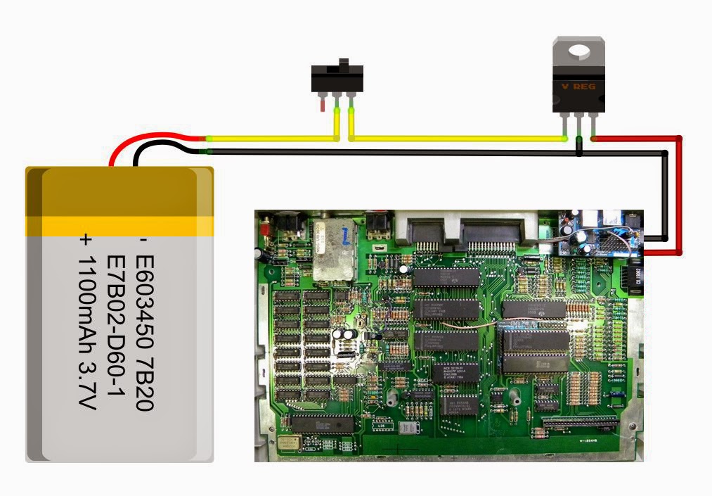
The design:


This design considers interrupting the 12V line. If you do it at the 5v stage after the regulator, you can easily solder the circuit directly to the 5v connector on the motherboard. However, this won't work best because the regulator will continuously draw current from your battery until depletion. Not good.

On the other hand, interrupting the battery feed directly like the diagram shows, will force you to add a secondary switch or de-solder the original switch.


Caveats on the design:


  • This design requires you to understand LiPo batteries because these are delicate and potentially dangerous. 
  • You will need good soldering skills and take the necessary precautions while connecting everything together and isolating the connections properly.
  • You will need a special charger to take care of the life of the battery as well as to prevent overcharge.


Regulator placement


The three legs of the power switch were de-soldered from the main board and isolated. This power switch now handles 12v instead of 5v.


Final battery placement
Project finished, ready for the final cover.

Charging


Charging gets accomplished using a special LiPoly charger directly to the balancer connector of the battery. That connector reaches the exterior of the case via the expansion port. If you look closely the last picture you will see a white connector sticking out.


After finished, I left it on by accident and noticed almost 3 hours later. 
The battery was at 11.7v, plenty of life left. But this definitely reminds me of the....


To Do


Add a low battery automatic shutdown to prevent damage to the battery.

Thanks for watching, stay tuned.