Sunday, December 16, 2012

Atari XF-551 Power DC supply mod

Find a need:
In the absence of the original 9V AC power supply required by the Atari XF-551 5.25 diskette drive, I decided to modify it to a brickless version.


Fill a need: 
Since the diskette drive is a standard IDE, we can use a standard IDE power supply (Any power brick capable of 15V and 2A should suffice.


First test: Will this work?

Note that if you feed the drive mechanism directly, you will not be feeding the main board of the XF-551, which means you will need to send power back to the board as you see in the picture below. The blue, red and green jumper wires are taking power from the connector board on the drive unit and sending it back through the original IDE connector and through the white ribbon wire to the main board.


Q: This is a power brick that supplies both 5V and 12V. Can I use something that provides only 12V?
While you can connect the power supply to the output of the 12V regulator and 5V regulator in the case your power can supply both voltages, you can't use a single 12V power supply and connect it to the OUTPUT OF THE RECTIFIER BRIDGE, which is a large dice attached to the dissipator. The reason being that you can't feed a 12V regulator with 12V.

You actually may be able to make it work with 12V to feed the whole board and drive, but chances are that the 12V regulator on the XF551 will deliver only 8 or 9V, which means your drive will be able to read diskettes but NOT WRITE or format anything.

Bottom line, if you can't find something that provides both 12 AND 5v, go for a 15 V or greater power supply. The on-board regulators will take it from there.


Now for the final mod in 10 simple steps:
There's a great space on the board, just inside the big heat dissipator to place this power unit.

1) Crack open the plastic case of your PSU, and use the guts, otherwise it will not fit in the drive.
2) De-solder and remove the original 9VAC jack on the main board of the XF-551 to avoid any accidental power supply mixture.
3) Hook the 12V line of the power brick to the 12V output of the 12V onboard regulator and the 5V line of your power brick to the output of the 5V regulator on the XF551.
4) Hook the GND line of the power brick to the GND on the main board of the XF-551.
5) Note that the rear switch has been disabled because the power jack was removed.
6) Pass the AC high voltage cable through the hole left by the absent power jack, and squeeze it with a zip tie to prevent accidental pulling.
7) Solder the mains power cable to the power brick.
8) Isolate the bottom of the power brick with tape and/or cardboard.
9) Stick the power brick to the original heat dissipator using double sided tape.
10) This may get hot, so a small fan will help to keep things cool.


Picture below shows how yellow cable feeds 12V to the output of the regulator, while the RED wire feeds 5V to the output of the 5V regulator.


and voliá the PSU inside the XF:


Isolation is important. This is live voltage. I isolated the bottom side of the PSU board with cardboard and tape. That's in case the heat melts down the glue and the PSU ends up falling on top of the main XF board.
Make sure the bottom part of the PS is adequately isolated.


You can see there's not a lot of weight added to the unit, and the result is as practical as you see below. The power plug in this particular case is a CEE 7/16 Europlug for 220VAC used by some countries in South America and Europe:


Ah.... there's one more thing.

The XF-551 LED mod.

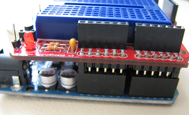
Now that your XF is open, add a red LED with a 330Ohm resistor. Hook it up to the 5V line and place the LED RIGHT BEHIND THE ORIGINAL LED.

The effect is the same as a bi-color LED. The new addition will lit as long as your disk drive has power.
When the drive is spinning, the green (original) led will light up, but it will mix colors with the existing RED led, providing a nice orange color.

Now you know when your drive is both powered and active, just like the 1050.


Enjoy!

Sunday, December 9, 2012

Hakko FX-888 (220V version) LED Hack

(c) EEVblog

As seen in Dave's EEVBlog, there's a quite handy hack to help you realize if your soldering iron is turned on or not by replacing the original LED with a bi-color two-legged LED.

Circuit being basically the same designed by Dave, my version features a small board with a cable extension to the LED.


It's a very simple project, check out the schematics below for the 110v version of the soldering station:

Fig 1. Schematics for the 110v version connected to the Hakko microcontroller open collector driver


Instructions for the 220v version of the FX-888: 

The 220v version happens to be different than the 110v version as it lacks of a microcontroller with an open collector driver. It actually has analog components (some Op amps and an opto isolator to drive the triac).

In this case, you just need to add a general-purpose opto coupler (2N36) as follows:

- Feed the opto coupler with the LED pins.
- Use the open collector of the opto coupler as a driver for the Dave Jones' version of the bi-color LED circuit.


Fig 2. Schematics for the 220v version connected to the original LED terminal


Mounting instructions:


Red and black wires are coming out from where the original LED was and they feed the optocoupler.

Ground terminal for the blinking circuit is taken from the negative side of the big capacitor, with easy access through the large resistor. The other end of this same resistor will be used to feed the Vcc line. There is a 10v voltage drop at this resistor.


The completed project working. The result is the exact same result you will see in the video below.

Now look closer. See how I covered the high voltage section with Gorilla tape while working? That's what smart people do. Please be careful when testing your circuit with the case open as 220VAC can kill you, or someone else -your cat included-.

Even simpler would be to drill a small hole on your iron and add a second LED hooked up to any Vcc point you may find on your board, just as I did with my old Atten station a couple of years ago, addressing the exact same LED issue.

And this is the original video with -as always- a great explanation from Dave Jones. Thank you Dave.


Thursday, May 17, 2012

LCD serial display out of an old Palm


Here's a good way of recycling old hardware: Use a palm device for your Arduino projects as a full-featured display.

You may want to get rid of the DB9 serial cable by just cutting it from the cradle and adding this small and cheap TTL-RS232 converter made of two transistors and four resistors. This circuit is a must, since the palm device uses RS232 levels to communicate while your Arduino or other micro will most likely use TTL levels.

Make sure you have some spare method to transfer software from the computer to the palm if needed, such as an SD card.


The circuit in place.

Rear view of the cradle.


The circuit fits nicely in the cradle, and the schematics are a modified design taken from Jim's Projects [Link] I made a different design choice here, and pull up the palm's RX line directly from +5V instead of doing it from DTR.


Schematics for the TTL-RS232 conversion circuit.

If you don't plan to use your Palm as a serial input device, then the TX line of the Palm (pin 2) is optional and you may wish to use only the output line of your microcontroller for a unidirectional configuration.


The finished setup at work. You can keep it handy in your workbench. The stand helps to keep it at a nice view angle.


Here you can see a repurposed Palm with PalmOrb software, which emulates a 16x4 LCD screen.
However you can use any standard Palm terminal software.

Plug and Play, no especial libraries required in the Arduino.

Enjoy!


Friday, April 27, 2012

DSO Nano made useful

DSO Nano V2 from Seeedstudio is a great hobbyist scope. Even though not Pro, it has proven to be very helpful for troubleshooting everyday situations.

There are two things however, where this scope really sucks: The stand, and the probe. The probes that come with it are cheap and ugly. The stand is a small piece of aluminum that will not hold the scope in place, making it difficult to work with.

So How to fixe them both?: You can get a standard probe from Amazon and adapt a small plug in just minutes. The stand is even easier if you happen to have a Panavise Jr: The DSO fits perfectly and stays rock solid!
This not only provides good angle for viewing but also allows single-handed operation, which for many will be the most important feature.

This is the best stand for the DSO Nano you will ever come up with.

Standard connector with the MONO metal plug:


The finished probe for the Nano:

Saturday, November 5, 2011

Arduino based Big Countdown Timer for New Year

The finished project at 11:39, before turning itself into a countdown timer. This timer has been in production since December 31st 2011 (upd: in production until 2020, decommissioned in July 2024)


October, 2011.
Inspired by Sparkfun's GPS clock, I decided to build my own version of a big countdown timer for New Year.

1) The concept
Dual function: A clock that starts at 11:00PM and simply shows the time for the entire hour. The idea behind it is to drive people's attention and let them know where the clock is.

I didn't  need a 24h clock, only something that tells the time from 11:00p to 11:58p and turns into a countdown timer for the last minute (the hour digits turns off and the countdown starts from second 59 to 00).

This approach saved me 6 segments and some space as well.

2) The clock itself:

I went as readable as I could, readable but portable. I used bright white LEDs (not ultra-bright) and some transistors. I happen to like Ben Krasnow's way of dealing with transistors.

This is what the first concept looks like:


3) Controlling the clock:
I used an Arduino and shift registers to control the segments, you can also use two Arduinos via I2C.

Two shift registers (74HC595) command the segments. 
An Arduino controls the shift registers, cycling about 150 times per second.

4) Time accuracy:

I wanted this thing to be accurate. The Atmega chip keeps track of time but they are not accurate enough over long periods of time, reason why I added a RealTime Clock Module.
Now, in order to have the RTC set at the right time, I added NTP Atomic Clock Synchronization capabilities through an Ethernet Shield.

Edit: After the first year into production, I decided to simplify the design by replacing the RTC+Ethernet shield with an LCD shield. This allows to manually adjust the clock while having a simpler setup.

In order to keep accuracy I use an NTP app in my iPhone and manually adjust the Arduino until it's synchronized by using the buttons available on the LCD shield.


5) The Design:

Before the shift registers, I used a two-arduino approach with served me well while shift registers were not available at the local store.

One GREAT source to  understand how the shift registers work is here at BLDR.ORG:


Check out bldr.org
Wiring of the 74HC595 I used. Check out bldr.org!


Back to the design board:

- I wanted to balance the amount of LEDs with functionality, and I ended up with 3 LEDs per segment.
- I could have gone with larger digits but I found that the size I went with was good enough.
- I wanted this to be both inexpensive and battery operated so I chose super-bright leds instead of ultra-bright.


6) The build:

This design calls for portable and lightweight, so let's use these convenient cardboard box lid.


I had these boxes in my storage room. I borrowed 3 lids.


Design of the digits. I drew them proportional to a small 7 segment display, under the assumption that it will increase readability.

Adding the LEDs to each segment:


8 segments in place. Each segment consists of 3 LEDs

Time to solder some wire, add current limiting resistors, some transistors and more resistors for their base just like the original design in paper.


Wiring at the back. The deadbug chip at the center is a resistor array.


First test:


First digit is complete. number 3 shows up.


And then another instance of the same digit plus a third that only does number 11, to get the project complete.

Front of the completed project, the three digits can be easily separated and piled up for easy transportation.


Back of the unit

Back of the unit


Portable mode!


Main controller


Test scenario: balcony. View from ground, several floors below:

Photo Enhanced ASA800 (Canon S3IS)

Normal Photo (ASA 100)

7) Power:

When all of the LEDs are on, consumption of the whole circuit is reasonably low.
This allows me to power the entire system with a 2000[mAh] 11.1[V] Lithium Polymer battery, making the clock 100% autonomous for the whole hour it is used.


Happy new year!   - Viña del Mar, Chile.

Wednesday, January 5, 2011

Arduino Protoshield Mods

Three simple and quick modifications that will transform your protoshield to a fully functional monster.

1) One millimeter higher:

Use 4 male header plastic bits. One for each of the 4 corners of the protoshield


This way, the protoshield stands a little higher than standard


But the benefits are great: You don't have to worry about shorts with the USB connector anymore.


Safe distance. At the same time, the protoshield is so much easier to plug and unplug now.


2) An LED tester

I don't use the BlueSmirf socket. But I connected the female headers because it provides an extra +5 and extra GND for prototyping. 
With a single 300 Ohm resistor between GND and the centermost pin (originally unused in the Sparkfun protoshield, you will be able to use the two centermost pins to test any led: Very handy!!!


3) A Power LED on top

If you add a resistor to +5  and an LED on top will serve as a Power LED on top of the protoshield. This is very handy to make sure your system is powered:


Enjoy!